
Industrial UV-LED Systems and System Architecture (365–405 nm)
UV-LED technology is widely used in industrial systems for processes such as curing, fluorescence inspection, and photochemical reactions. Compared to traditional UV sources, UV-LED systems allow precise control of irradiance, rapid switching, and compact integration into industrial machines.
Applications range from curing of resins, adhesives and coatings, to machine vision & inspection, photocatalytic reactors for air and water purification, additive manufacturing, and medical uses such as photocrosslinkable hydrogels.
To meet these requirements, Zirqle, LuxaLight and MaNima Technologies together provide a modular system topology:
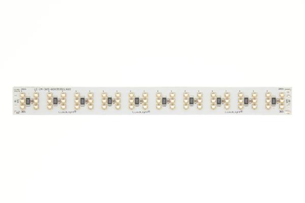
Zirqle LED engines – high-performance UV-A modules with integrated NTC monitoring, designed for precision, stability and scalability in industrial environments.
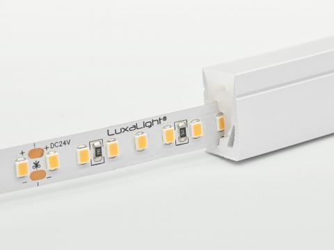
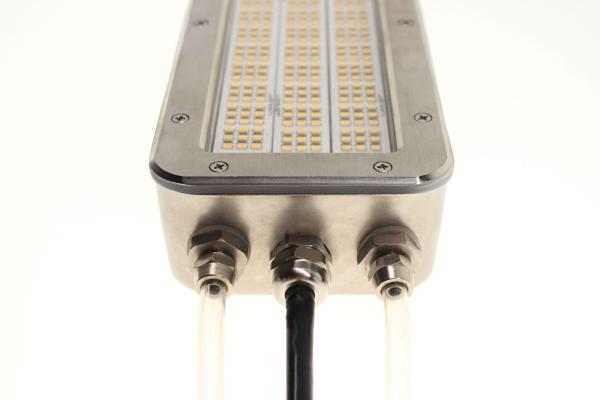
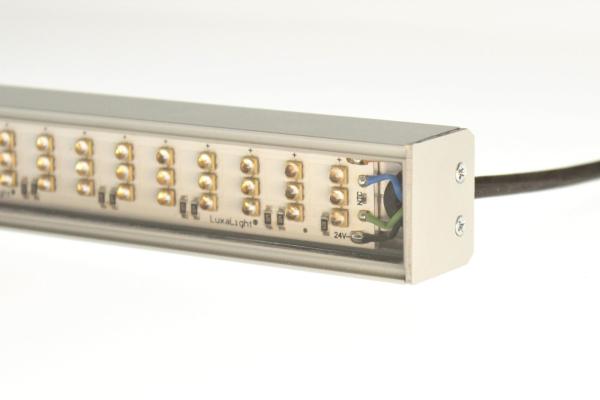
LuxaLight fixtures – scalable from compact R&D setups to large industrial panels, available in 365, 395 and 405 nm, with options for optics, housings and cooling (passive or active water/glycol).
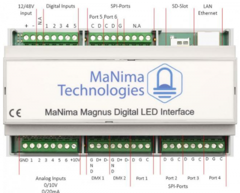
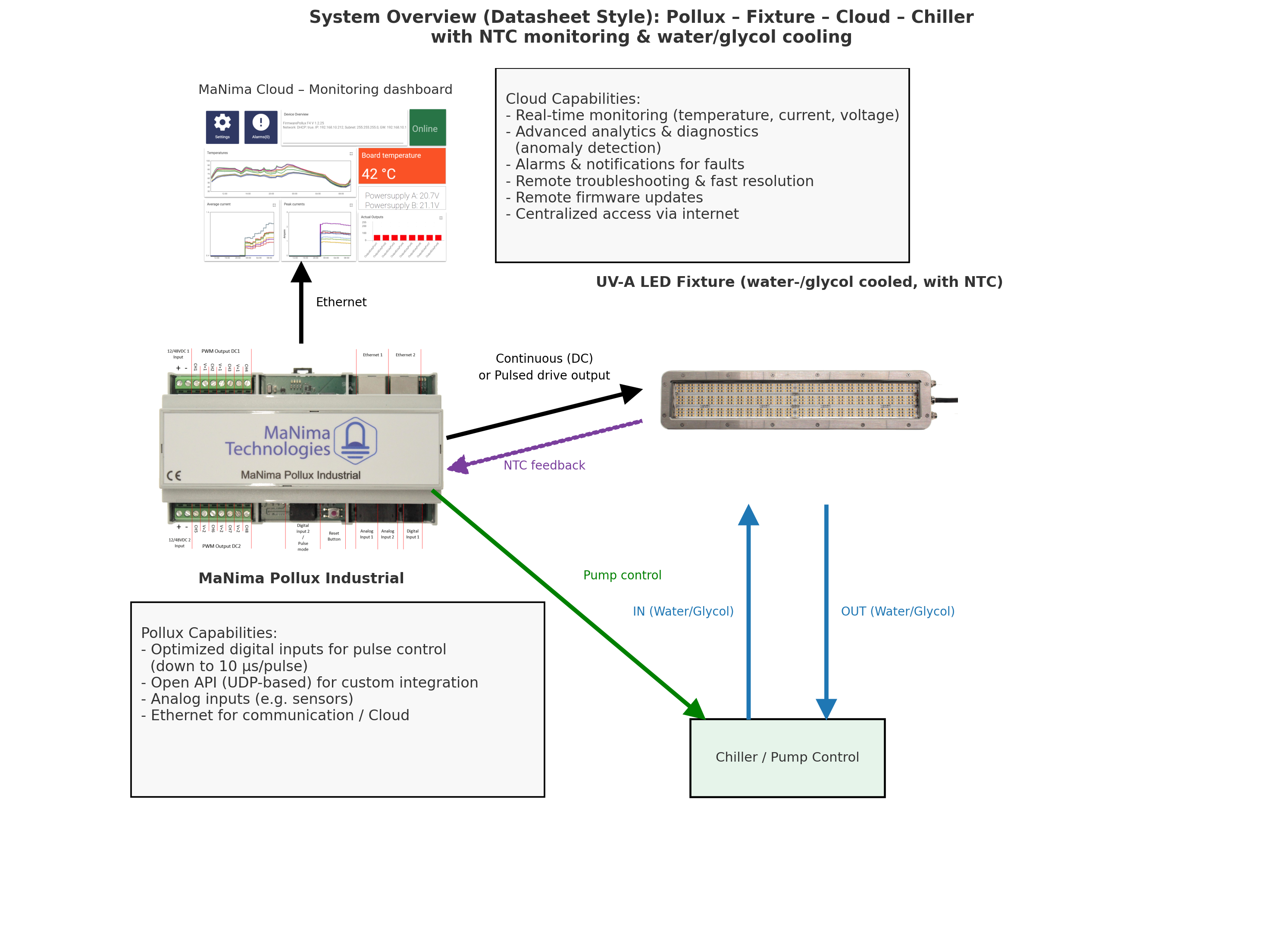
MaNima Pollux drivers – support microsecond-precision pulsing and strobing, integrated NTC feedback, and connectivity through industrial protocols.
Cloud monitoring – real-time insight into voltage, current and temperature, including alarms and data analytics.
By combining these elements, a complete system topology is created in which LED engines, fixtures, drivers and monitoring are perfectly aligned. This ensures the highest irradiance at the target surface, enabling processes to run faster, more consistently, and with improved product quality.
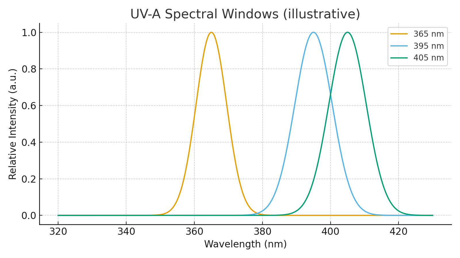
365 nm – highest photon energy | 395 nm – penetration/efficiency balance | 405 nm – near-visible, inspection & catalysis
| Wavelength | Photon Energy (relative) | Characteristics | Typical Applications |
|---|---|---|---|
| 365 nm | ★★★ (highest) | Strong absorption by photoinitiators; shallow penetration | Thin coatings, transparent adhesives, photochemistry, fluorescent detection |
| 395 nm | ★★☆ | Balance between penetration and efficiency | Inks, coatings, adhesives, inline curing, process monitoring |
| 405 nm | ★☆☆ (lowest) | Near-visible; deeper penetration into bulk materials | Photocatalysis (TiO₂), thick coatings, vision & inspection |
Lamp versus LED
Traditional UV-A lamps emit in all directions (360°), causing more than half of the energy to be lost. UV-A LEDs, on the other hand, feature a directed emission angle (typically 120°), ensuring that nearly all emitted photons reach the target surface effectively.
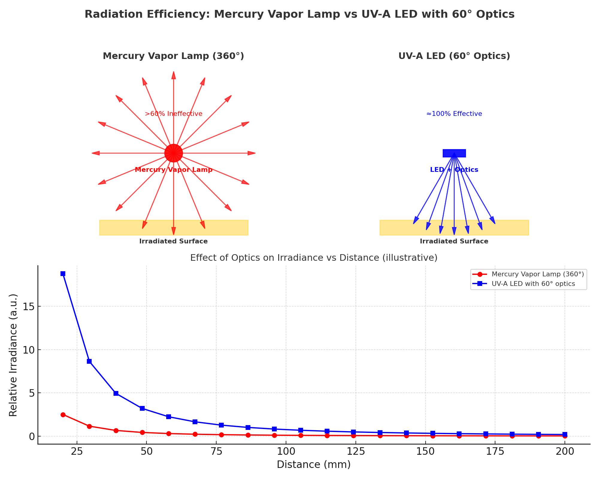
Comparison of a conventional Mercury Vapor Lamp (360°) and a UV-A LED with 60° optics.
Mercury lamps lose more than 60% of their radiation due to uncontrolled emission, while LEDs concentrate nearly all energy on the target surface. This results in up to 8× higher irradiance and faster, more consistent processes.
Focus and Optics
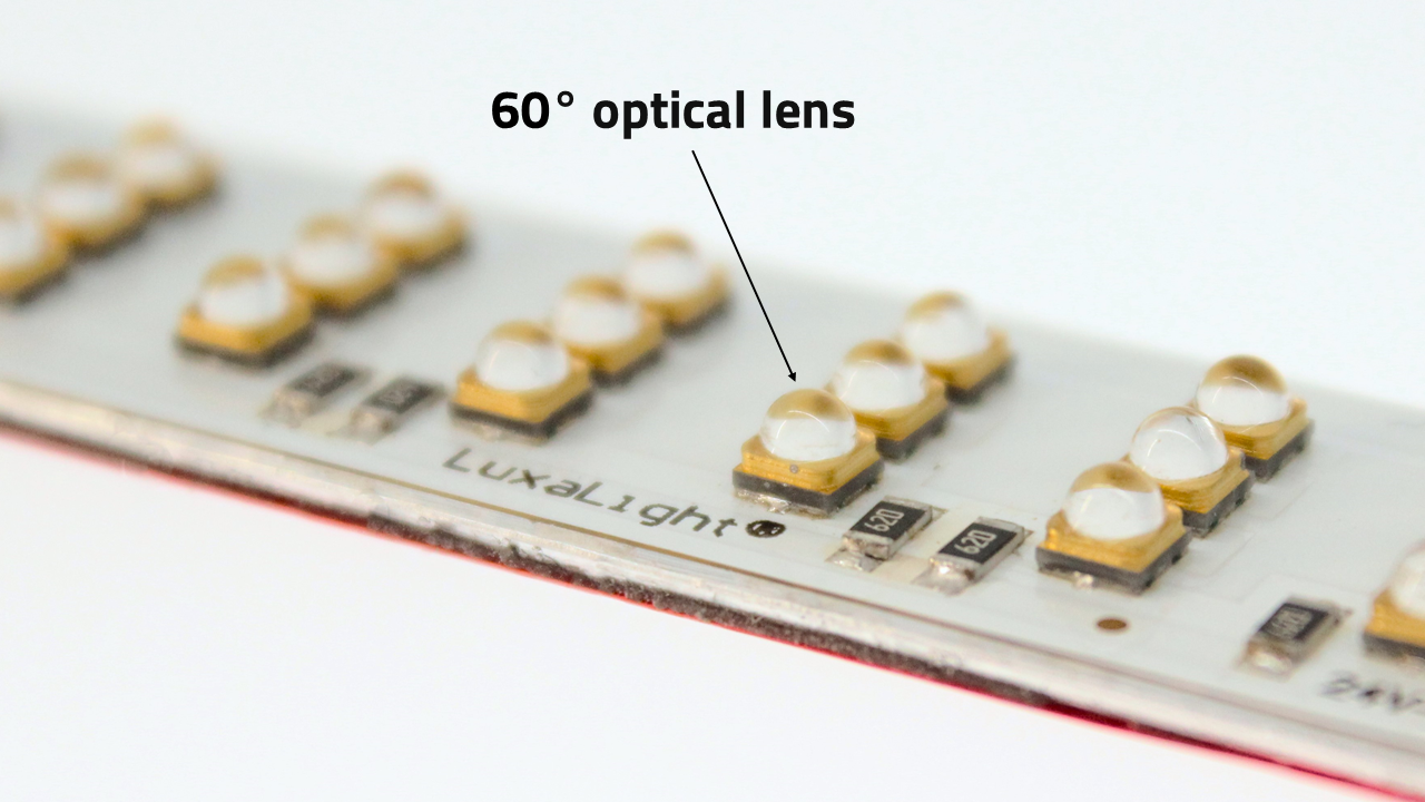
By combining LED modules with optics, the emission angle can be further reduced, for example to 60°. This results in a much higher irradiance (W/m²) at the target surface, without increasing the total power consumption.
This allows an engineer to choose between:
- Narrow beams with high intensity for curing, vision and precision applications.
- Wide beams without optics for homogeneous illumination of larger surfaces, such as reactors.
MaNima System Topology
Built for precision, scalability and reliability — the MaNima topology merges UV-A LED engines, fixtures, intelligent drivers and cloud monitoring into a unified, modular system.
This architecture empowers engineers to synchronize and optimize UV-A irradiation at 365, 395 and 405 nm across a variety of industrial applications — from curing and machine vision to additive manufacturing and photocatalysis. Below is the structured overview of system layers and their engineering benefits:
| Layer | Components | Key Functions | Benefits for Engineers |
|---|---|---|---|
| 1. Drive Control (Pollux) | MaNima Pollux drivers | • Continuous & pulsed current down to 10 µs resolution • Configurable pulse width, duty cycle, triggers • Interfaces: Configurator, UDP API, industrial protocols (Ethernet, digital I/O) | • Precise synchronization with PLCs, machine vision and reactors • Flexible integration into existing automation |
| 2. LED Engines & Fixtures (Zirqle & LuxaLight) | UV-A engines (365, 395, 405 nm) with NTCs Modular fixtures with passive aluminium or active water/glycol cooling Optical modules (e.g. 60° quartz lenses) | • Thermal monitoring at PCB level • Passive or active cooling depending on power level • Optics increase irradiance up to 8× | • Scalable from R&D setups to full production • Higher irradiance and stability at the target |
| 3. Monitoring & Thermal Feedback | Embedded NTC sensors Integration with chillers and pump controllers Pollux closed-loop regulation | • Real-time feedback of temperature, current and voltage • Automatic adjustment of drive current • Closed-loop thermal management via chiller/pump control | • Stable irradiance even under high duty cycles • Extended LED lifetime • Safe operation at high power |
| 4. Cloud & Analytics | MaNima Cloud dashboards & API | • Real-time logging (T, V, I, irradiance) • Predictive maintenance • Remote diagnostics & firmware updates | • Full process transparency • Reduced downtime • Future-proof integration |
LED Engines and Fixtures
The MaNima system supports a wide range of UV-A light sources, provided by both Zirqle and LuxaLight. Engineers can choose between individual LED engines or complete fixtures depending on the application requirements.
LED Engines – Compact UV-A modules (365, 395, 405 nm) with integrated NTC sensors for precise thermal feedback. Ideal for custom integration or OEM designs.
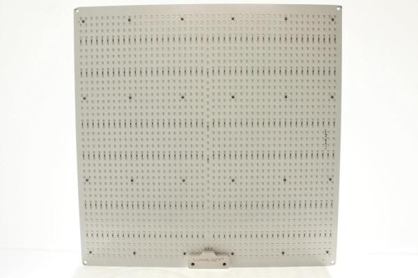
Plate Fixtures – Modular flat-panel assemblies for homogeneous irradiation over larger surfaces. Suitable for curing, coatings and inline inspection.
Water-Cooled Fixtures – High-power solutions with integrated water/glycol channels and stainless steel housings. Designed for continuous operation in demanding industrial environments.
Moulded (Encapsulated) Fixtures – Fully potted fixtures with protective encapsulation for harsh environments. Resistant to dust, moisture and chemicals, ensuring long-term stability.
This modular portfolio enables engineers to select the optimal configuration — from single engines for R&D setups to rugged, water-cooled fixtures for large-scale industrial processes.
Irradiance and Energy Dose
In UV-LED applications, the process result is primarily determined by the combination of irradiance and exposure time.
Irradiance describes the optical power per surface area and is usually expressed in:
W/m² or mW/cm²
The energy dose describes the total amount of UV energy received by a surface:
J/cm²
The relationship between these quantities is:
energy dose = irradiance × time
For many industrial processes – such as UV curing, polymerization and photochemical reactions – the required energy dose determines the process result. Irradiance determines how quickly this dose can be delivered.
In continuous production lines, the energy dose is often determined by the combination of irradiance and conveyor speed.
Design Parameters of UV-LED Systems
When designing or integrating a UV-LED system, several parameters must be considered.
Important design factors include:
- working distance between LED and target
- optical beam angle
- desired irradiance on the surface
- required energy dose
- homogeneity of the illumination field
- thermal dissipation of the system.
The final configuration of a UV-LED installation is usually determined by a combination of these factors. By varying optics, distance and module configuration, the system can be adapted to specific process requirements.
Modular LED engines make it possible to scale irradiance by combining multiple modules or by adjusting the optical configuration.
Driver Architecture: Constant Voltage and Constant Current
UV-LED systems can be driven in two different ways: constant current (CC) or constant voltage (CV).
Constant Current
With a constant-current driver, the LED current is directly regulated. The driver automatically adjusts the output voltage to maintain a fixed LED current.
Characteristics of CC systems:
- precise current control
- stable optical output
- protection against overcurrent.
This architecture is often used in integrated LED luminaires where the driver is part of the fixture.
Constant Voltage
In constant-voltage systems, the power supply delivers a fixed voltage, for example 24 V or 48 V. The LED module contains the internal LED string configuration and stabilization components.
Characteristics of CV systems:
- modular system architecture
- easy expansion with multiple LED modules
- fast PWM control possible
- good integration with industrial controllers.
Many modular UV-LED systems are therefore designed for a constant-voltage architecture, enabling scalability and fast pulse control.
Thermal Management
The performance of UV-LEDs strongly depends on the junction temperature of the LED chip.
As temperature increases, several effects occur:
- reduction of optical output
- shift of the peak wavelength
- accelerated degradation of the LED.
Therefore, thermal management is an essential part of industrial UV-LED systems.
UV-LED performance strongly depends on junction temperature. Higher temperatures lead to lower optical output and reduced lifetime.
Common solutions include:
- aluminium MCPCB substrates
- passive heat sinks
- forced air cooling
- water-cooled modules for high-power systems.
Temperature monitoring is often applied to protect the system against overheating and to ensure stable operating conditions.
Modular UV-LED Building Blocks for OEM Systems
Industrial UV-LED installations are often built from separate functional modules.
A typical system consists of:
- UV-LED engines
- optical modules or fixtures
- power supply and driver systems
- industrial controllers for monitoring and pulse control.
This modular architecture allows UV systems to be flexibly configured and integrated into existing machines.
OEM systems can therefore easily be adapted to:
- different working distances
- varying irradiance levels
- specific process geometries.
By combining multiple LED engines, optical power can be scaled without changing the basic system architecture.